Appendix 3 - Complex NUMA Systems
Some server systems have NUMA architectures that require careful configuration and device usage. Dual-socket AMD-based systems are the main example.
This AMD document describes the processor and supporting component architecture, along with guidance on BIOS settings for various workloads. One of the key parameters is NUMA Nodes per Socket (NPS), which divides the resources associated with a processor into NUMA domains. In practice, for GPU nodes this is often dictated by Nvidia or other GPU vendors, commonly setting NPS = 4. On a dual socket system, this sets up 8 NUMA domains.
The following simplified diagram illustrates the two processor sockets, the External Global Memory Interconnects (xGMI) that connect the NUMA domains, and a set of I/O devices hanging from them.
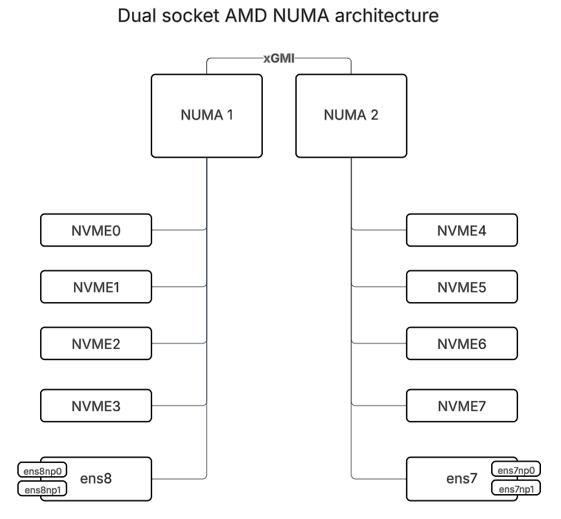
The result is that I/O between devices on different NUMA domains, especially between sockets, can incur a significant latency penalty. This has been measured at customer sites, with up to 50% impact on throughput between devices on different NUMA domains.
There are several commands that can be used to determine the NUMA architecture of a system and attached or installed devices. Some commands yield different levels of detail or even what devices are included, depending on the platform. Commands like dmidecode, lspci (with -vvv or -tv options), and lstopo (if installed) can yield system architecture. The files under /sys/class are dynamically generated and are a consistent way to determine the NUMA configuration we need. The following grep commands show all the devices and their NUMA node in one concise output.
# grep . /sys/class/net/*/device/numa_node

/sys/class/net/ens7f0np0/device/numa_node:7

/sys/class/net/ens7f1np1/device/numa_node:7

/sys/class/net/ens8f0np0/device/numa_node:2

/sys/class/net/ens8f1np1/device/numa_node:2

# grep . /sys/class/nvme/nvme*/device/numa_node

/sys/class/nvme/nvme0/device/numa_node:0

/sys/class/nvme/nvme1/device/numa_node:1

/sys/class/nvme/nvme2/device/numa_node:2

/sys/class/nvme/nvme3/device/numa_node:3

/sys/class/nvme/nvme4/device/numa_node:4

/sys/class/nvme/nvme5/device/numa_node:5

/sys/class/nvme/nvme6/device/numa_node:6

/sys/class/nvme/nvme7/device/numa_node:7
Note that depending on how NVME devices enumerate, the NUMA nodes may not match the above output. The lower numbered half of the NUMA nodes are associated with the first CPU socket, NUMA 1 in the diagram above, and in AMD’s documentation, while the higher numbered half of the NUMA nodes are associated with the second CPU socket and NUMA 2.
NVME Devices and RAID
The NVME devices above on NUMA nodes 0-3 are associated with the same processor, so if RAID is used, one RAID array should consist of NVME drives on these NUMA nodes, and another array with NUMA nodes 4-7.
NICs
In the example above, the dual port NIC with ens7f0np0 and ens7f1np1 is on NUMA node 7 and ens8f0np0 and ens8f1np1 are on NUMA node 2. So, devices nvme0-3 should be accessed via ens8f0np0 and ens8f1np1, and devices nvme4-7 should be accessed via ens7f0np0 and ens7f1np1.
Bonding
You can bond interfaces to improve performance and redundancy, but you have to be careful. A bond should include only interfaces on the same NUMA (socket). In our example, we have 2 dual-port NICs, so bonds should be created using both ports of one NIC in a bond. Keep in mind that for RDMA, bonds must use ports on the same dual port NIC, rather than ports on two different NICs even if they’re on the same NUMA node.
IP Assignment
Each NIC (if not bonding) or each bond needs an IP address. These IPs can be on the same subnet or different subnets. For Tier 0 use cases, different subnets work well when clients have interfaces on each subnet.
Hammerspace Volume Configuration
The last element of getting workloads to avoid crossing NUMA boundaries is on the Hammerspace side. We need to tell Hammerspace that certain volumes perform better using specific IP addresses to direct traffic over the right interfaces. In Hammerspace, each volume can have sets of Additional IPs and Excluded IPs. So it’s a simple matter to specify those per volume using the GUI, CLI, or API.
You can use the volume-add command with the --additional-ip and --excluded-ip parameters to add a volume and specify the correct IPs in one step, or you can specify the IPs later using the volume-update command with --additional-ip-add and --excluded-ip-add. This part of the configuration applies the same, whether the Hammerspace volume corresponds to a RAID array or individual drive on the Tier 0 (or LSS) node.
anvil1> volume-update --name AZ1:node101::/mnt/hsvol0n1 --additional-ip-add 10.200.200.170/32

anvil1> volume-update --name AZ1:node101::/mnt/hsvol0n1 --excluded-ip-add 10.200.100.170

ID: 167a2a56-e36e-4806-8034-c4b885ef42fb

Name: AZ1:node101::/mnt/hsvol0n1

Internal ID: 34

Discovered addresses:

[IP: 10.200.100.170/32, Port: 2049, NetId: tcp, NodeNum: 0]

Excluded IPs: [10.200.100.170]

Additional IPs:

[IP: 10.200.200.170/32, Port: 2049, NetId: tcp, NodeNum: 0]

Effective IPs:

[IP: 10.200.200.170/32, Port: 2049, NetId: tcp, NodeNum: 0]

Path: /mnt/hsvol0n1

State: OK

Access type: Read Write

Node: AZ1:node101

Oper state: Up

Admin state: Up