Installing the Metadata Server (Anvil)
Anvil is installed from a bootable ISO image and contains its own appliance operating system. No other OS license is required. The installation process has been designed to request all required information up front, even before an additional node is installed.
Two-node HA cluster
The ISO allows you to set up several architectural variations; however, the basic workflow described in the following sections installs a two-node HA deployment.
| It is highly recommended to use a high availability (HA) deployment for the Anvil metadata server. That includes a minimum of two Anvil nodes, a resilient network configuration, and mirrored metadata drives. A two-Anvil HA deployment also requires an external quorum server; see Installing and Configuring a Quorum Server. |
It is supported to use two or three Anvil nodes in a high-availability architecture. When deploying a three-node HA configuration, the third node is added after the initial installation and configuration of the first two nodes.
The installation of a two-node Anvil, high-availability (HA) cluster takes approximately 20 minutes. Most of that time is spent waiting for the system image to be installed and the network parameters to be configured.
The installation of DSX node(s) can be done in parallel and may start before the Anvil installation is complete, but it will not finish until the Anvil nodes are fully installed.
Example installation workflow
In the initial part of the two-node HA installation, you will select a block device to boot from the ISO, determine the installation product (Anvil) to install, validate the hardware, and assign roles to network interfaces. The second part of this installation configures the first Anvil node of the HA cluster. You will repeat these steps to install the second Anvil node of the HA cluster.
Part 1: Initial Part of the Installation
-
Confirm that the Virtual Machine (VM) or bare-metal server meets the minimum system requirements.
The installer re-checks these requirements later, on the Virtual Hardware Validation screen, and reports anything undersized as a caution rather than an error. Cautions do not stop the installation, so it is worth confirming sizing now rather than deciding at the validation screen whether a caution matters. -
Load the ISO image and power on the VM or bare-metal server.
-
Ensure that the server boots from the ISO image rather than from its own drives.
Before the first boot, confirm that the CD/DVD device is listed above the hard drive in the server’s firmware boot order. Many virtual machines place the hard drive first by default. When that happens the server boots whatever is already on its disks and the installer never appears, which looks like the ISO failing to load even though the ISO was never reached.
On a virtual machine, also confirm that the virtual CD/DVD drive is set to connect at power on. A drive that has the ISO attached but is not connected behaves exactly like an empty drive.
-
At the Hammerspace boot menu, select Install Hammerspace and press Enter.
The highlighted default on this menu is Boot from next device in boot order, and the menu acts on that default automatically after a short countdown. Press an arrow key as soon as the menu appears to stop the countdown, then select Install Hammerspace. If the countdown expires, the server boots from its drives instead; reset the server and try again. Installing Hammerspace is destructive to the existing data on the local drives. 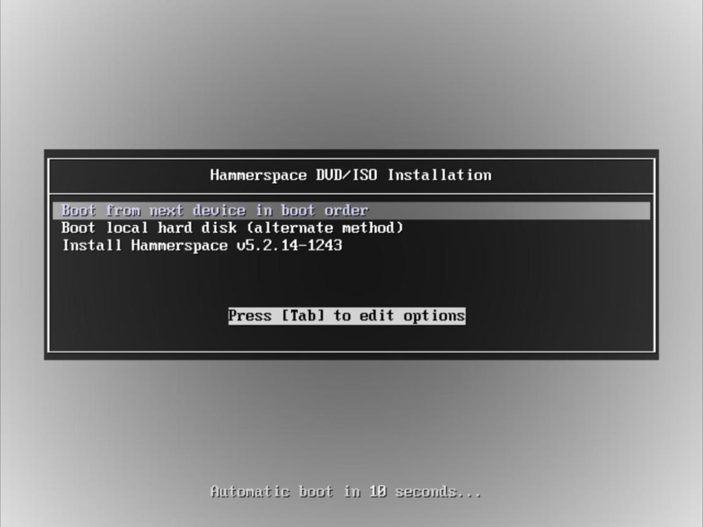 Figure 1. Hammerspace boot menu
 -
The installation program automatically discovers local storage devices. Select the boot device for installation and then Install to continue.
Boot drives should be at least 200GB. See the Anvil requirements table for full sizing guidance. Choose the boot device by its size rather than accepting whichever device the installer arrives with selected. The pre-selection is not always the device you want: the same physical disk can enumerate as
sdaon one node andsdbon an identically built one, so the pre-selection lands correctly on one server and on the wrong disk on the next.Selecting a device other than the first one listed adds a caution that the installation may fail to boot unless the firmware can boot from that device. The caution names the device concerned. This is a general warning rather than a detected fault.
All discovered block devices will be overwritten during the installation. Any existing data on these devices will be erased. 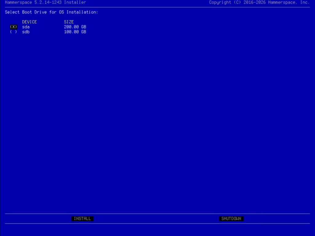 Figure 2. Boot drive selection screen
 -
A confirmation dialog asks you to approve overwriting the drives before anything is written. Select Yes and press Enter.
This dialog defaults to No. It names the device the boot image will be written to, so it is also the last chance to catch the wrong disk having been selected on the previous screen. Read the device name before confirming. 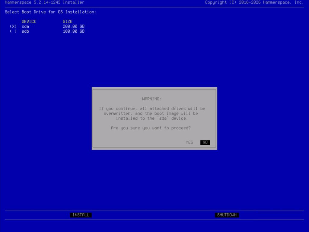 Figure 3. Overwrite confirmation dialog
 -
After you confirm, the installer writes the boot image and then reboots using the installed image before any further input is required.
Writing the boot image can take a considerable time, and slower storage makes a large difference. When installing from virtual media attached to a local computer, the installation may appear to make no progress even though it is progressing slowly. This often happens when the progress bar reaches 60%. The progress bar runs twice. It fills once for Writing boot image, then resets and fills again for Verifying boot image. Reaching 100% the first time is the halfway point, not the end of the write. After the reboot, the server displays Hammerspace system booting… for around 90 seconds before the next screen appears. This pause is expected and is not a failure. 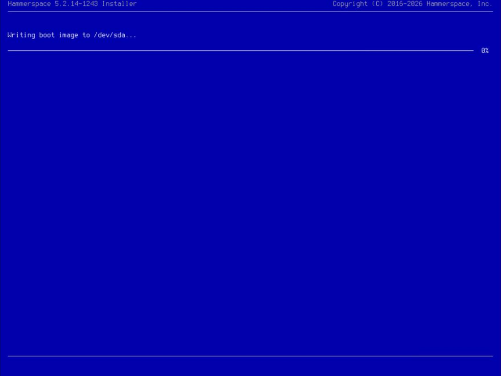 Figure 4. Installation progress screen
 -
Review the End User License Agreement (EULA), then select Accept.
The EULA is also available online on the Hammerspace End User License Agreement page of the Hammerspace website. 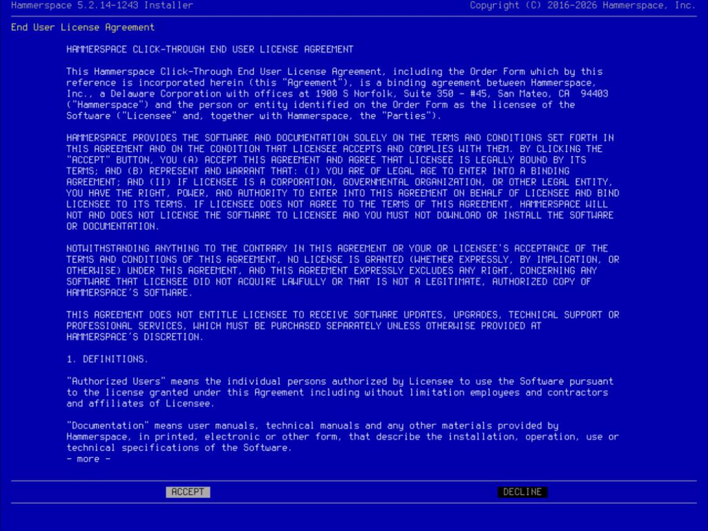 Figure 5. EULA acceptance screen
 -
Select the Anvil product type, then continue configuring the installation. The Virtual Hardware Validation screen displays.
The installer usually arrives at this screen with a product type already selected, based on the resources it detects. Confirm that the selection is the one you intend before continuing. 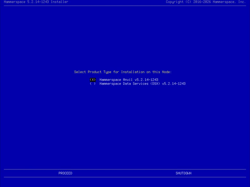 Figure 6. Select the product type
 -
Confirm that the discovered hardware has been validated, then select PROCEED. In the example below, the installer has flagged cautions for the missing CPU and memory reservations, and for local storage that is smaller and fewer in number than recommended. It is strongly recommended that a production installation in a virtual environment always use CPU and memory reservations.
Everything on this screen is reported as a caution, never as an error, and PROCEED stays available regardless. The installer will let you continue with an undersized system, so the decision about whether a caution is acceptable is yours to make here.
Two cautions are worth expecting rather than troubleshooting:
-
Memory allocated at exactly the minimum is still flagged. A guest sees slightly less memory than the hypervisor allocates to it, so a VM built to the documented minimum presents just under the bar. Allocate somewhat above the minimum rather than exactly at it.
-
Reservations are checked separately from size. A correctly sized VM still shows CPU-reservation and memory-reservation cautions until the reservations themselves are set on the hypervisor.
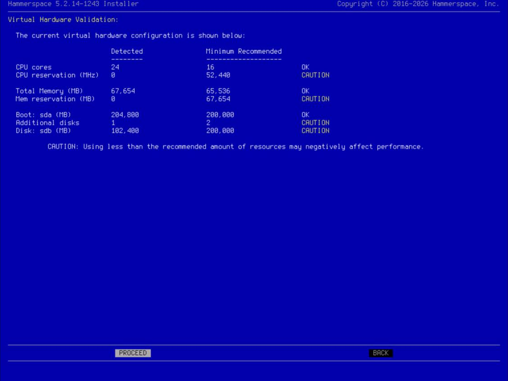 Figure 7. Resource validation check
 -
-
If the installer finds an earlier Hammerspace installation on the drives, it asks whether to reuse the previous settings. Select No to configure the node from scratch.
This prompt appears only when the drives already hold a Hammerspace installation, so it is not seen on a new server. It defaults to No. Answering Yes pre-fills the configuration form from the previous installation, which is useful when you are deliberately rebuilding a node to the same specification and misleading when you are not. 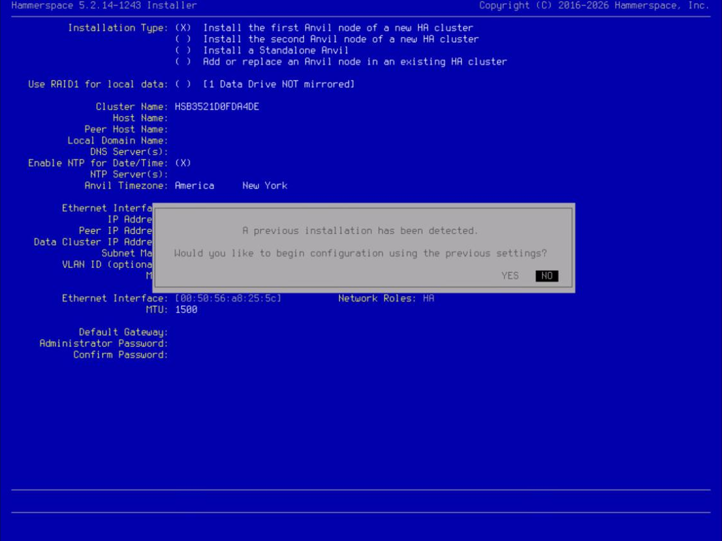 Figure 8. Previous installation detected
 -
Configure networking by optionally bonding interfaces together and then assigning roles to the available network interfaces.
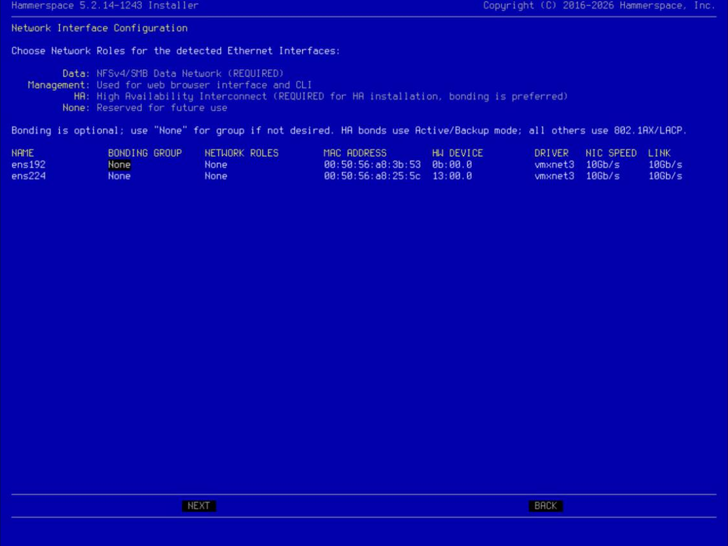 Figure 9. Configure networking
Hammerspace only supports LACP (Link Aggregation Control Protocol) bonding for non-HA roles. HA bonding is active-backup only. Whether to bond is a decision about your environment, not a Hammerspace requirement:
-
Consider bonding when you have two or more physical NICs cabled to switch ports that already support LACP, and you want the network to keep working if one link or cable fails. This matters most for the High Availability role: if the HA interconnect between Anvil nodes has no fallback path, losing that single link can prevent the nodes from communicating during a failure.
-
Selecting
Noneis a reasonable choice when you only have one interface available for a role, when redundancy is already handled below the guest (for example, NIC teaming on the hypervisor’s virtual switch), or when your switch ports aren’t configured for LACP yet and you’d rather complete the install now and revisit networking later.
Bonding is only offered when two or more interfaces could actually be bonded together. If each interface is attached to a different network, no bonding peer is available and the column stays empty.
This choice isn’t final. Interface and bonding configuration can be changed after installation from the Admin CLI.
-
-
To create a bond, use the tab or arrow keys to select an entry in the BONDING PEER column and then press Enter. Then use the arrow keys to select an interface to bond with and press Enter.
-
To assign roles, use the tab or arrow keys to select an entry in the NETWORK ROLES column and then press Enter. Use the arrow keys to choose from the list of role combinations, and press Enter to assign the highlighted combination. When all interfaces have been assigned, select NEXT and press Enter.
Roles are assigned to an interface as a predefined combination, not as individual roles that you switch on and off. The list offers combinations such as
Data, ManagementorData, Management, HAas single choices.The list also narrows as you work. Once one interface has taken a role, the combinations offered for the remaining interfaces drop that role, so the choices available on the second interface are fewer than those on the first. This is the installer preventing a conflicting assignment rather than a fault.
On a server with a single interface, the installer may arrive with a combination already assigned.
The network roles provide the following functionality:
See the Firewall Port Requirements section for port-level detail per role.
-
Data: Used to connect all storage clients and servers (including DSX nodes). NFS and SMB data traffic flows across the data Network, as well as some Inter-node communication.
-
Management: Used for management and monitoring tasks. This role is not used for file sharing, data movement, or HA cluster communications.
-
High Availability: Used for peer-to-peer communications between the nodes in an HA deployment. Select the interface on this network that is configured to be connected to the second node on a private interconnect. For bare-metal deployments, a back-to-back network cable connection is preferred (no switch needed).
All Anvil installations require at least one network interface with management, data, and high-availability roles. It is supported to share all roles on one interface, including the HA role. When sharing all roles on an interface, ensure the interface speed is at least 10 Gbit/s.
-
It is also possible to configure additional interfaces once the system is installed. Hammerspace supports floating IP addresses and VLAN assignment to interfaces. All these configuration settings are accessible in the Admin CLI interface after installation is complete.
| After the installation has completed successfully, eject the CD-ROM or remove the ISO image from the virtual machine. This matters most when you have moved the CD/DVD device above the hard drive in the boot order, because the server will otherwise return to the installer on its next restart instead of booting the system you just installed. |
Part 2: Installing the First Anvil Node in the HA Cluster
Continue the installation by selecting the installation type and providing the required details. For this example, we are installing the first Anvil of a new HA cluster.
-
Select the Installation type: Install the first node of a new HA cluster, then enter the other installation and configuration details on the page.
In the Installation type list, the arrow keys move the highlight but do not commit the choice. Press Space to select the highlighted installation type before moving on to the rest of the form. 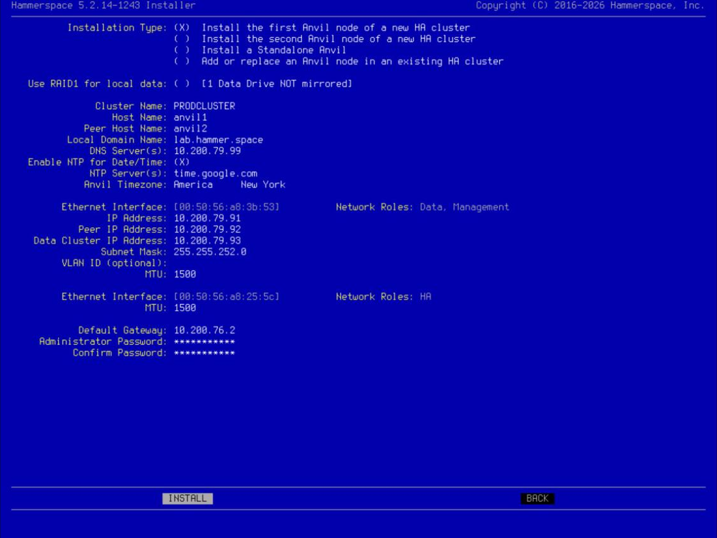 Figure 10. Installation type and first-node configuration details
Where:
-
Cluster Name: This is the SMB Server Name and the Cluster Name. The installer supplies a generated name; replace it with a name that means something in your environment.
The SMB Server Name can be changed when joining Active Directory. -
Use RAID1 for local data: Mirrors the local metadata drives. This option requires two or more data drives. With a single data drive the field reports that the drive is not mirrored and cannot be selected.
-
Host Name: Enter the host name of the first node.
-
Peer Host Name: Enter the hostname of the second node.
-
Local Domain Name: Enter the name of the local domain.
-
DNS Server(s): Use comma-separated entries for multiple DNS servers. Required for NTP and Active Directory support. The Anvil and DSX nodes communicate with each other using only IP addresses; however, any communication outside of the nodes may require DNS.
The installer does not test whether the DNS servers are reachable while you are filling in the form. That test happens later, after the configuration is committed, during the network-start phase. An unreachable DNS server therefore surfaces partway through configuration rather than at the field itself. -
NTP Server(s): Use comma-separated entries for multiple NTP servers. This is required for Active Directory support and strongly recommended for all other configurations. The Anvil servers will act as NTP servers for the DSX nodes.
Identifying an NTP server by hostname requires a DNS server to be configured. To use NTP without DNS, enter the NTP server’s IP address instead. -
Timezone: Set the time zone for the installation.
-
Ethernet Interface: For the Management and Data Network Interfaces, configure the following:
-
IP Address
-
Peer IP Address
-
Data Cluster IP Address: The floating IP address that clients and the Management GUI use to reach the cluster. This address automatically moves to whichever Anvil node is currently active, so it stays reachable regardless of which node is primary at any given time.
-
Subnet Mask (or Prefix)
Data and management interfaces must be on different subnets if configured at separate interfaces. -
VLAN ID (optional): Enter a value here only if VLAN tagging must be performed by the Anvil or DSX node.
-
MTU size: The default MTU size is 1500 bytes. To use Jumbo frames, change the MTU size to match your network infrastructure. Typically, the correct value is 9000.
-
Default Gateway: This is the IP address of the Default Gateway.
-
Administrator password: Sets the password for the admin user. The password must contain a mix of letters, numbers, and symbols, and must meet a minimum length requirement.
The interface carrying the High Availability role is configured differently from the data and management interfaces: it has an MTU setting only. It does not ask for an IP address, peer IP address, cluster IP address, or subnet mask, because the HA interconnect addresses itself automatically. An empty-looking HA block is correct, not an incomplete form. -
-
Review the configuration for accuracy. If all settings are correct, select INSTALL and press Enter to continue.
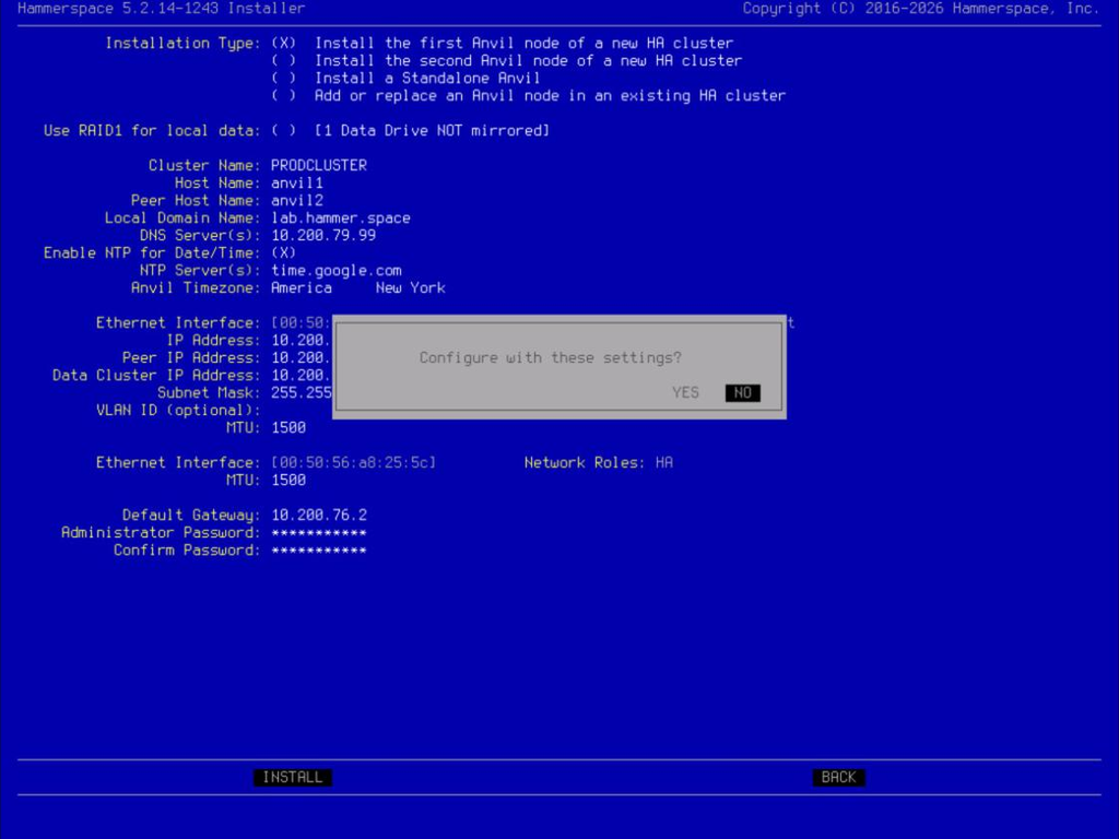 Figure 11. Confirming the configuration before installing
 -
Select Yes and press Enter to confirm.
Once the installation of the first node completes, the node waits for its peer and displays the address that the second node needs.
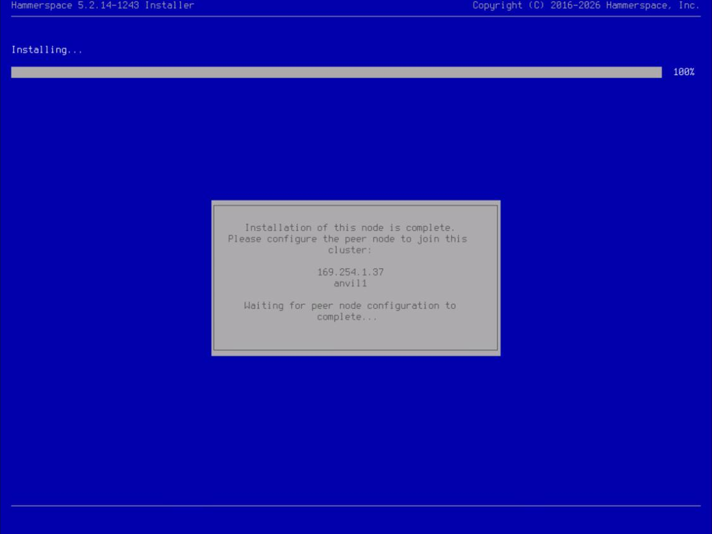
Make a note of the address displayed on this screen. It is a link-local address on the private interconnect, in the 169.254.x.x range, rather than the data-network address you assigned to the node. You are asked to confirm it when installing the second Anvil node, and the second node’s discovery may offer several similar addresses without labelling which is which, so the exact value matters.
|
| The installation is not complete, and the cluster cannot be used until the second Anvil node of the cluster has been successfully added. |
Continue to Part 3: Installing Second Anvil Node in HA Cluster below to install the second Anvil node.
Part 3: Installing Second Anvil Node in HA Cluster
Complete the following steps to create the second node on the high-availability cluster:
-
Repeat all of Part 1: Initial Part of the Installation (Steps 1–14) on the second node, through the network role assignment.
-
Next, select the Installation type: Install the second Anvil node of a new HA cluster.
As on the first node, the arrow keys move the highlight but do not commit the choice. Press Space to select this installation type. 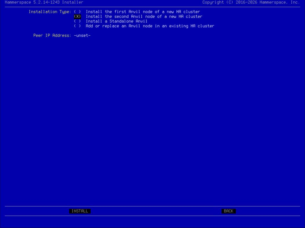 Figure 13. Selecting the second-node installation type
Selecting this installation type reduces the form to a single field, Peer IP Address. The second node does not ask for a host name, IP address, subnet mask, gateway, DNS or NTP servers, timezone, or administrator password. It inherits all of them from the first node across the private interconnect once the two nodes have found each other. A form with only one field on it is the expected result, not a screen that has failed to load. -
Press Tab on your keyboard to move the cursor to Peer IP Address and press Enter. The peer IP address will be automatically discovered using the private interconnect.
Discovery may return several addresses, listed without labels to identify which node each belongs to. Select the exact address that the first node displayed on its waiting for peer screen. If you have multiple clusters sharing the same heartbeat network, this is also how you make sure you are joining the right one. -
Once the Peer IP address is selected, select Install and press Enter. Always double-check that the peer IP address matches the one displayed on the console of the first node.
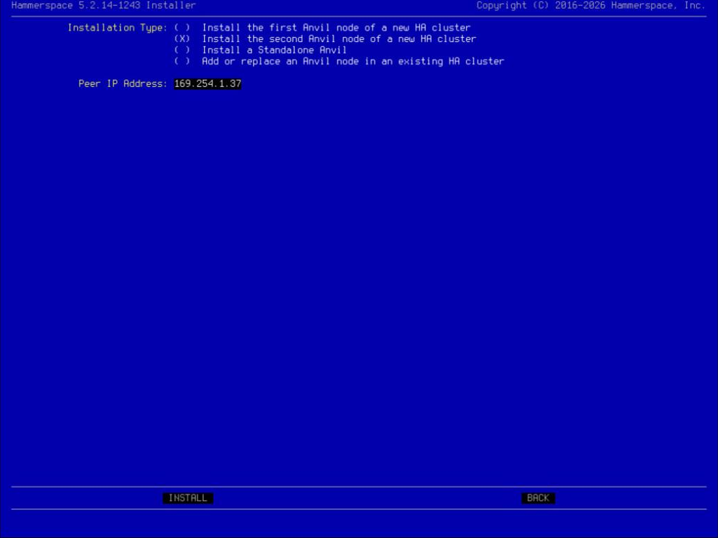 Figure 14. Peer address selected, ready to install
 -
Select Yes and press Enter.
-
The HA cluster and network settings are automatically configured, and the installation starts.
-
The following screen is displayed after the installation has completed:
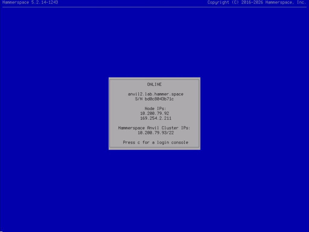 Figure 15. Second node installation complete
Both nodes should now report the same Hammerspace Anvil Cluster IP. If they do not, the two nodes have not joined the same cluster and the peer address selected in the previous step is the first thing to check. -
Validate the installation by opening a web browser and going to the URL for the Management Graphical User Interface (Management GUI).
The URL for the Management GUI is the Anvil Data Cluster IP — the floating address you assigned during the first node’s installation, not the address of either individual node. In this example, it is
https://192.0.2.10:8443.The Management GUI answers on port 8443 and on the standard HTTPS port, so https://<cluster-ip>;reaches it as well. A plainhttp://<cluster-ip>;address is redirected tohttps://<cluster-ip>:8443. -
When the web interface displays, log in using the admin credentials specified during installation to confirm successful installation.
 Figure 16. Logging in to the Management GUI
| If you installed from an ISO image in a vSphere environment, you must disable time synchronization settings for each VM. See the time synchronization section for information. |
Optional: Adding a Third Node to a Two-Node HA Cluster
Complete the following steps to add an optional third Anvil node to a two-node HA cluster:
-
Ensure the two-node cluster is installed and configured. The third node is added after the initial installation using the console installer.
-
Repeat all of Part 1: Initial Part of the Installation (Steps 1–14) on the new node, through the network role assignment.
-
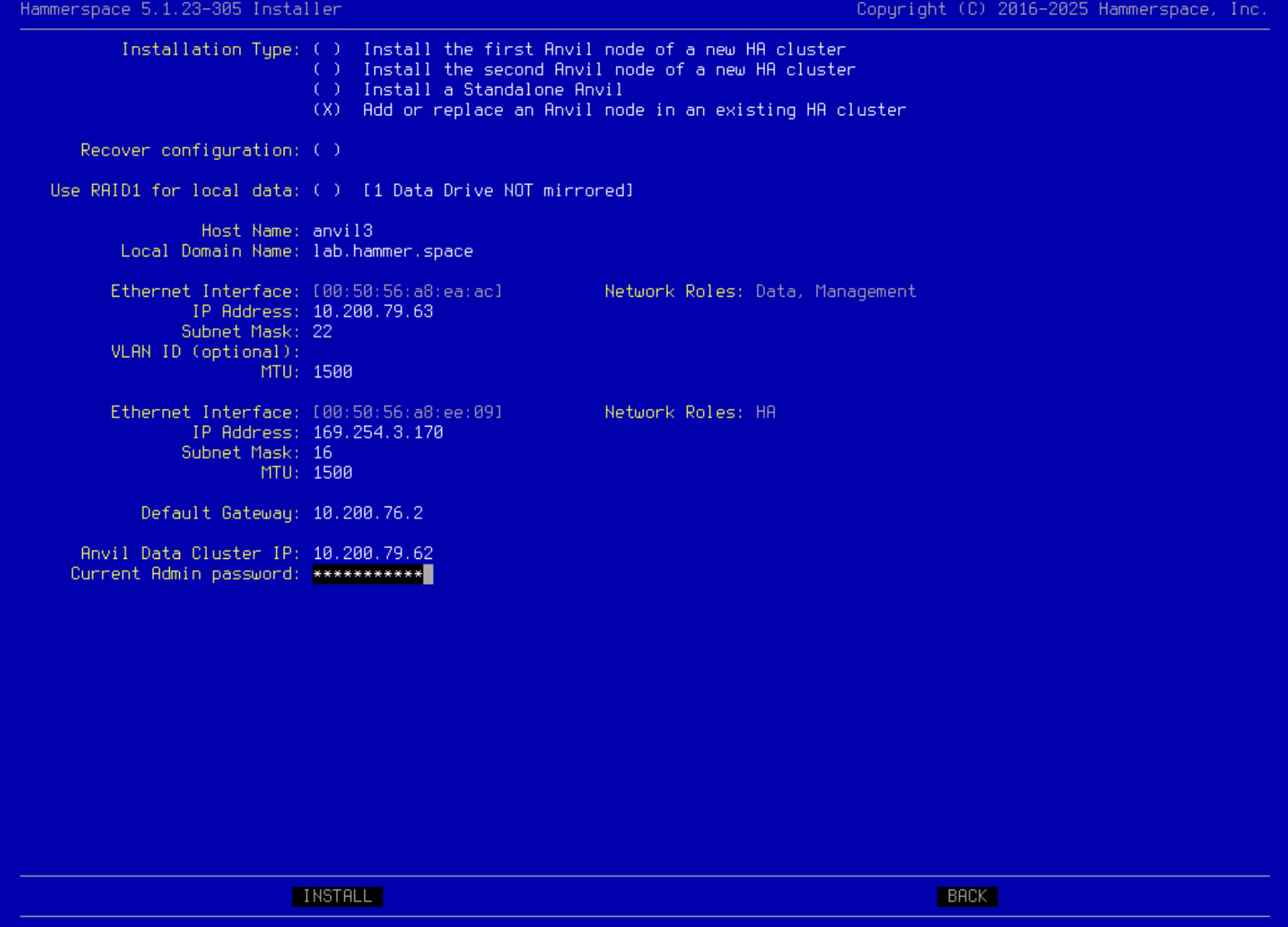
On the Installation type configuration screen, select Add or replace an Anvil node in an existing HA cluster.
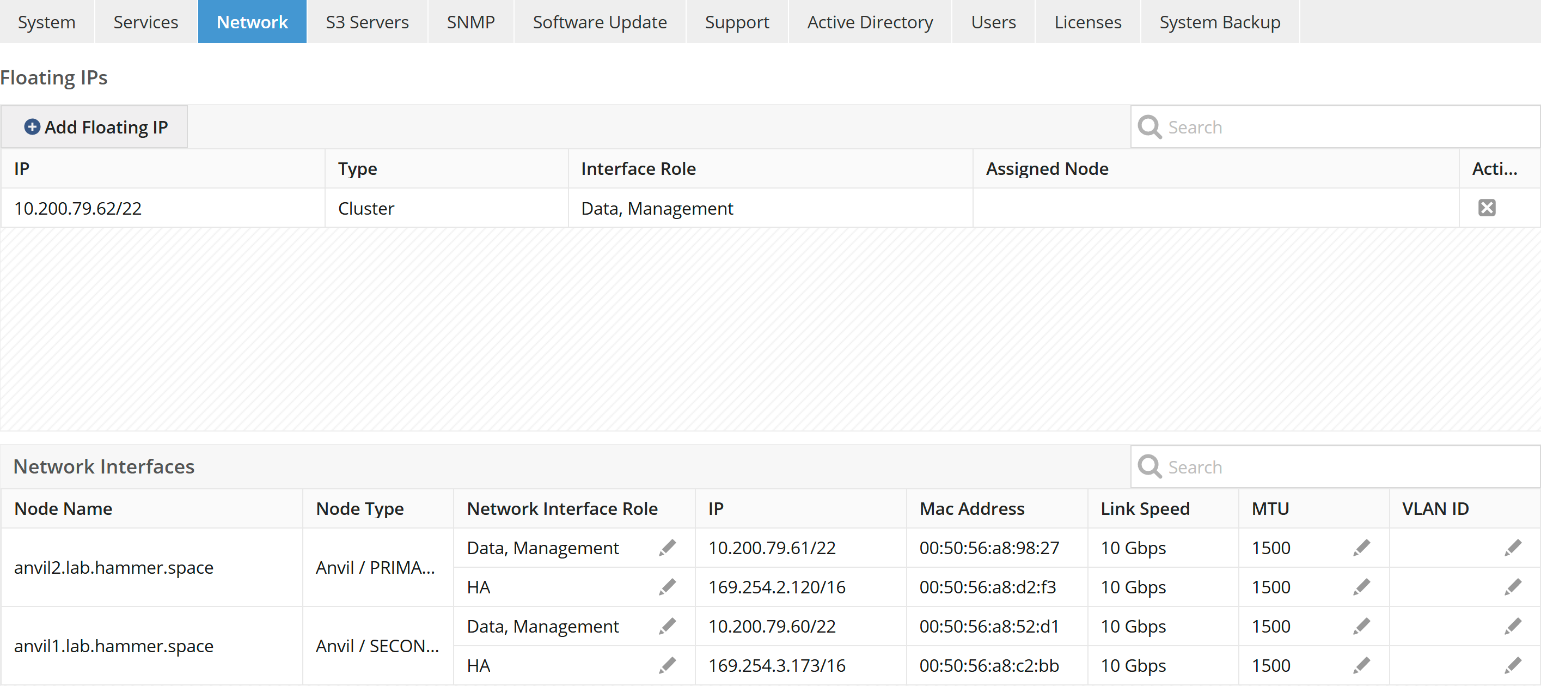
Do NOT check the Recover configuration option. That workflow replaces a failed Anvil node. The example below shows how to add a third Anvil node to a configuration with a dedicated HA network. In this configuration, the HA interface IP address must be manually specified.
To view the existing IP addresses that are in use by Hammerspace product nodes, navigate to Administration > Network in the Management GUI.
Pick an address that does not conflict with an existing address on the HA interconnect network.
Fill in the configuration information in the console installer.
-
Press Install, and after a few minutes, the third HA Anvil will be available in the cluster.
If the cluster is configured with very large metadata drives, it will take several minutes for the metadata drives to finish their background synchronization. -
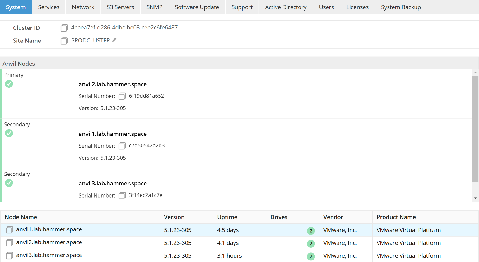
Validate that the third node has successfully been added by logging into the Management GUI and navigating to Administration > System. In the example below, there are three Anvil nodes: one Primary and two Secondary.
Recovering a Failed or Missing Anvil Node
Use this procedure when an Anvil node in an HA cluster must be reinstalled — for example, after a failed software update, hardware replacement, or an accidental reinstall.
Cancel Any Stuck Software Update
If the surviving Anvil still shows a software update in progress, cancel it from the Admin CLI on the surviving Anvil.
-
View the in-progress update task:
software-update-status -
Cancel the task using its ID:
software-update-cancel --task-id <ID>
Reinstall the Failed Anvil
-
Install the same software build that the surviving Anvil is running on the replacement node.
-
During installation, choose the installation type Add or replace an Anvil node in an existing HA cluster.
-
Use the same network and identity settings the failed node had.
-
At the end of installation, the installer displays a CLI command to run on the surviving (primary) Anvil.
Rejoin the Cluster
Run the command provided by the installer on the surviving Anvil to rejoin the reinstalled node into the HA cluster, then verify cluster health: node-list should show both Anvils with HW state OK and Node mode ONLINE, and the Metadata servers line of cluster-config should list both, one with Role: Primary.